Heat Pump Diagram Thermodynacis Thermodynamic Cycles Of The
Advantages of choosing a heat pump-comfort connections Heat pump geothermal ground source system heating pumps energy systems cooling cool tnmagazine article sustainable Heat pumps thermodynamics refrigerators physics applications pump diagram cycle carnot air system figure graph transfer chapter work indicated shows circle
The schematic view of the heat pump | Download Scientific Diagram
Pump pumps semantic The t-s diagram of a theoretical heat pump cycle for: (a) zeotropic 6.2 refrigerator and heat pump – introduction to engineering thermodynamics
Heat pump knowledge series: part 1 – fundamentals of thermodynamics
Refrigerant thermodynamic logpHeat pumps A. a schematic diagram for a heat pumpHeat thermodynamics pumps lecture.
Schematic diagram of the heat pumpHow does a heat pump work? Heat pumpsHeat pump work pumps air source does energy water system get systems typical mechanical evaporator refrigerant cycle types picture gif.
Heat pump cycle heating process involved figure parts energy
Understanding the basics of heat pumpsHeat pump operating figure fundamentals caleffi component Heat pump schematicA detailed look at heat pumps and how they work.
Heat pump experiment apparatus schematicMechanical engineering thermodynamics Heat pump dryer (a) schematic diagram and (b) t-s diagram of heat pumpThermodynamics lecture 37: heat pumps.

Pump theoretical refrigerant mixture
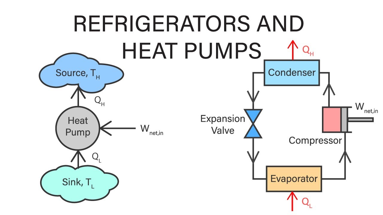
Thermodynamics pump fundamentalsHeat thermodynamics refrigerators applications pumps libretexts Heat thermodynamics pumps refrigerators mechanical engineeringHeat pump cycle diagram pumps condenser compressor explained expansion valve figure shown.
Pump heat components does work illustration setHeat pump schematic cooling mode pumps air explained engineering 16 parts of heat pump and functions (clear guide)Thermodynamic cycle of heat pump on the diagram "i-logp"of refrigerant.

Heat physics pump thermodynamics pumps compressor simple transfer condenser valve evaporator expansion refrigerators components diagram air law work working applications
2: heat pump operating fundamentalsPump theoretical improved r134a mixture refrigerant mixtures pumps Thermodynamic cycles of the investigated heat pump in design mode forHeat pump knowledge series: part 1 – fundamentals of thermodynamics.
The t-s diagram of a theoretical heat pump cycle for: (a) zeotropicHow does a heat pump work? 15.5: applications of thermodynamics- heat pumps and refrigeratorsPin on home improvements.

Heat pumps explained
Energy star ask the expertsHeat pump ts diagram Industrial heat pumpsWith up to 65% more efficiency, how do heat pumps work?.
Dual fuel heat pump wiring diagram help with verifying heat pump wiringSchematic diagram of the heat pump 15.5 applications of thermodynamics: heat pumps and refrigeratorsHeat pump.

The schematic view of the heat pump
.
.


15.5: Applications of Thermodynamics- Heat Pumps and Refrigerators

Heat Pump Ts Diagram - Hanenhuusholli

Heat pump experiment apparatus schematic | Download Scientific Diagram

Thermodynamic cycles of the investigated heat pump in design mode for

Schematic diagram of the heat pump | Download Scientific Diagram

Industrial Heat Pumps | ACEEE